P Jfet
- Home Products Discretes & Drivers JFETs 2N5462 2N5462: Small Signal JFET P-Channel Datasheet: JFET Amplifier P-Channel Rev.
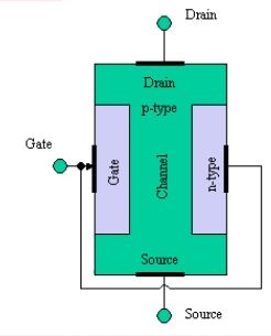
- P-Channel Operation of JFET. For turning ON P-channel JFET, negative voltage can be applied across the drain terminal of the transistor w.r.t source terminal such that the drain terminal must be appropriately more negative than the source terminal. Thus, the current flow.
- P Channel Jfet Working
- Jfet P Channel Datasheet
- Jfet Switch Circuit
- P Channel Jfet Transfer Characteristics
Ciircuits, Diagrams & Symbols Includes:
Circuit symbols overviewResistorsCapacitorsInductors, coils, chokes & transformersDiodesBipolar transistorsField effect transistorsWires, switches & connectorsAnalogue & functional circuit blocksLogic
JFET; a p-channel JFET can be made by transposing the p and n materials. All JFETs operate in the depletion mode, as already described. Figure 4 shows the typical transfer character-istics of a low-power n-channel JFET, and illustrates some important fea-tures of this type of device. The most important characteristics of the JFET are as follows.
Field effect transistors, FETs come in a large variety of different types. Each type of FET has its own circuit symbol, so it helps to understand the different types of FET and their circuit symbols to enable the circuits to be read accurately.

P Channel Jfet Working
Junction FETs or JFETs were the first type of FET and these have a distinctive symbol showing the diode junction. Insulated gate FETs, including MOSFETs have circuit symbols that indicate the insulation on the gate.
Jfet P Channel Datasheet
Obviously dual gate FETs have two gates and both need to be incorporated into the circuit symbol.
Jfet Switch Circuit
P Channel Jfet Transfer Characteristics
| FET Circuit Symbols | |
|---|---|
| FET Type | Circuit Symbol |
| J-FET N channel | |
| J-FET P channel | |
| Basic enhancemment insulated gate FET (MOSFET) N channel | |
| Basic enhancemment insulated gate FET (MOSFET) P channel | |
| Basic enhancemment insulated gate FET (MOSFET) N channel no bulk semiconductor | |
| Basic enhancemment insulated gate FET (MOSFET) P channel no bulk semiconductor | |
| Basic depletion insulated gate FET N channel | |
| Basic depletion insulated gate FET P channel | |
Note: The circuit symbols for FETs are marked with D, G and S for drain, gate and source. These letters are not normally included in circuit diagrams, but they are included here for clarity and explanation.
More Circuits & Circuit Design:
Op Amp basicsOp Amp circuitsPower supply circuitsTransistor designTransistor DarlingtonTransistor circuitsFET circuitsCircuit symbols
Return to Circuit Design menu . . .
